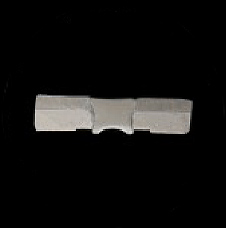
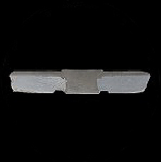
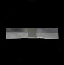
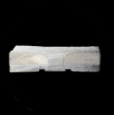
Flush Self-Pierce Riveting
Introducing FSPR
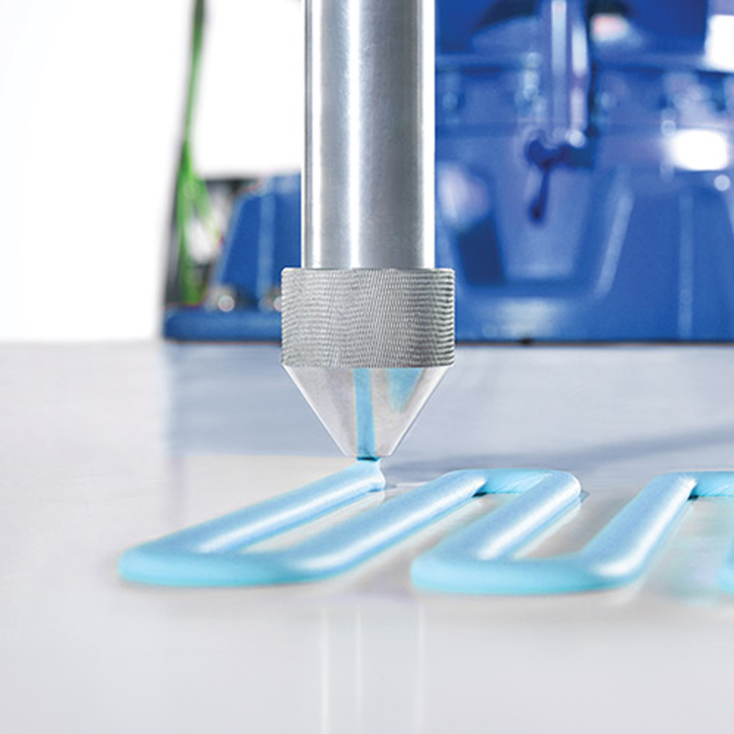
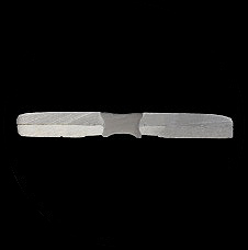
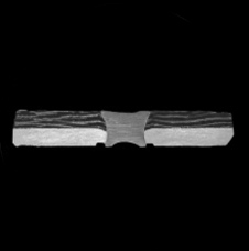
FSPR self-pierce riveting process is realized by a simple punch and die operation which automatically feeds, punches, inserts and locks the self-piercing rivet to produce a solid joint in one high-cycle operation.
Creation of a Fastened Joint
3 STEPS
STAMPING
PIERCING
FORMING
High joint integrity. Fatigue resistant.

Flush Self-pierce Riveting (FSPR®) is a method of joining two or more pieces of identical or dissimilar materials using a rivet, without the need for a pre-drilled hole. It is an automated repeatable process that requires no hole preparation and delivers high static strength similar to, or better than, spot welding.

The process produces a fatigue resistant joint that is stronger than spot welding and less susceptible to corrosion.

The basic self-pierce riveting process involves driving a roll-formed or machined rivet at a high force through the material layers to be joined, into a die which extrudes the material during piercing to form a joint. It is flush on both sides with the rivet completely embedded on the punch side.
works well with

Deep drawing steels
with Rm up to 1000 MPa

High-strength steels
with Rm up to 1600 MPa

Hot-stamped steels
with Rm up to 1800 MPa

Aluminium and alloy
(pressure cast, extruded, sheet)

Multilayer stack-ups with
dissimilar materials

Adhesive was a
middle layer

Non-ferrous metals &
non-metallic materials
(copper,
magnesium, and carbon fiber)
as a middle layer

need to knows
1
For multi-layer thick plate connections, die side materials should be ≥ 0.5mm
2
Thick ⇌ thin,
hard ⇌ material combinations
3
The thickness of the bottom plate can exceed 1/5 of the total
riveted thickness
4
Best joint strength will result from piercing the softest and/ or thinnest material first
SPR
VS
FSPR
Universe of Materials
01

Hot stamped steel
(Softening treatment required)

01

Hot stamped steel

02

High strength steel
(≤1200 MPa)

02

High strength steel
(≤1800 MPa)

03

Die-cast aluminium
(Elongation ≥ 10 %)

03

Die-cast aluminium
(Elongation ≥ 3 %)

04

Aluminium alloy

04

Aluminium alloy

05

Carbon brazing
(High risk of cracking)

05

Carbon brazing

06

Low and medium strength steel

06

Low and medium strength steel

07

Universal steel

07

Hot stamped steel

08

Galvanised sheet

08

Galvanised sheet

09

Die-cast magnesium

10

Magnesium alloy

11

PP material

sample combinations
H3
1.2mm  AZ318
1.2mm  6061AL
Material stack-up: 2.4mm
H7
1.85mm Carbon Fiber
2mm 7075AL
Material stack-up: 3.85mm
H7-165
1.5mm 7075AL
2.5mm AM50
Material stack-up: 4mm
H9
1.2 mm  HSS
3 mm AL (Die-Cast)
Material stack-up: 4.2mm
H11-220
2mm HSS
3mm AZ31B  
Material stack-up: 5mm
H11-260
1.2mm CR260 (Cold Rolled)
3mm AL (Die-Cast)
2mm CR420 (Cold Rolled)
Material stack-up: 6.2mm
RECOMMENDED MATERIAL STACK-UPS
1
The thickness of the bottom plate should be at least 1/5 of the total thickness of the combined plate.
2

Convex side: high-strength metal materials, such as plated steel, hot-formed steel, high-strength steel, etc.

Middle layer: medium and low strength and non-metallic materials, such as carbon fiber, medium and low strength steel, aluminum alloy, etc.

Concave side: medium and low strength metal materials, such as medium and low strength steel, aluminum alloy, etc.

3
When two-layer board materials are riveted together,  the allowable tensile strength of the material on the convex side is within 1800MPa, and that on the concave side within 1000MPa;
4
When multi-layer board materials are riveted together, the tensile strength of the material on the concave side minus the tensile strength of the middle layer material is ≦ 250Mpa.
- Difference value = positive: concave material is “harder “than middle layer material  
- Difference value = negative: concave material is “softer” than middle layer material
5
When thin plate is on the punch side, and thick plate is on the concave side, the riveting strength is better, but the thick plate is also allowed on the punch side;